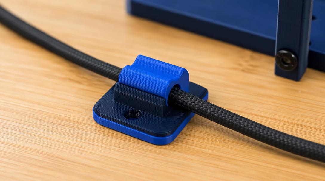
Cable Clip Design for FDM 3D Printing: A Guide to Securing Cables Without Crushing Them
3D-printed cable clips make it easier to organize cables around a desk, panel, or device, but simply keeping a cable in place is not enough. If the clip is too tight, it can put pressure on the insulation; if it is too loose, it may not support the cable. A thin root can also break after repeated opening and closing. A successful FDM design uses controlled clearance, sufficient wall thickness, and a suitable print orientation based on the cable’s diameter and how the clip will be used.
First, define the cable and where it will be used
The first design input is the cable’s dimensions. For a round cable, measure its outer diameter at several points; for a flat ribbon cable, record its width and thickness separately. Include any thick jacket or braided sleeve in your measurements. If you plan to hold multiple cables in one clip, design a separate slot for each one. Forcing them all into a single narrow opening can make installation difficult and cause the cables to press against one another.
Decide what the clip needs to do: will it hold the cable against a surface, guide it through a channel, or open and close by hand when needed? For a fixed cable guide, the cable’s path through the clip and the mounting screws are important. For a flexible clip that will be opened frequently, the opening width and the root of the clip arm matter most. If the clip will be used near moving machinery, sharp edges, high temperatures, or in an electrical-safety context, do not assume that a simple desk clip is suitable; assess its suitability separately against the requirements of the cable and environment.
Clearance, opening, and grip geometry
Rather than making the clip’s internal dimensions an exact copy of the cable’s diameter, consider how the cable compresses. A stiff cable with a thick jacket may flex slightly, while a soft or braided cable may deform under the same pressure. So, treat the cable-enclosing slot and the entry opening as separate features in your design. The inner slot should be close enough to support the cable, while the opening should be wide enough to let you insert the cable without bending it excessively. There is no universal clearance value; printer calibration, filament, cable jacket, and model geometry all affect the result.
The safest approach is to prepare a short test piece containing only the cross-section before printing the full-size clip. You can include several different slot or opening dimensions in the same model. Check whether the cable inserts easily, tends to pull free, or shows marks on its outer jacket. When choosing the final dimensions, prefer an option that keeps the cable in place during normal use but still lets you remove it without tools—not one that holds it by crushing it.
| Design feature | What to check | Decision criteria |
|---|---|---|
| Inner slot | Cable diameter and jacket flexibility | Does it guide the cable without squeezing it? |
| Entry opening | How often the cable will be installed and removed | Can the cable be inserted and removed by hand? |
| Clip root | Repeated opening and bending | Is there a sharp, abrupt transition at the root? |
| Mounting base | Screws, tape, or another fastening method | Is the load transferred evenly to the surface? |
| Print orientation | Opening force on the clip arm | Will the layers be stressed in a direction that could separate them? |
Shape and print orientation to reduce breakage
If the clip arm joins the base at a sharp inside corner, stress can concentrate in a small area. Joining the root with a broad curve and avoiding sudden changes in arm thickness can help spread the load over a wider area. However, a thicker design is not always better: if the clip needs to flex, an unnecessarily thick arm can increase the force needed to install the cable. Adjust the geometry to suit its purpose, and do not assume that simply increasing infill will solve the problem in a load-bearing functional part. The outer walls, cross-section, layer orientation, and mounting base all work together.
Print orientation matters because FDM parts are built in layers. Instead of loading the clip arm in a direction that pulls the layers apart, consider an orientation that lets the layers carry the load. This choice may affect support requirements or surface appearance; inspect the part in your slicer and check how the layers run through the critical root area. If the part will face substantial force, a safety risk, or repeated long-term cycling, do not use it for a critical application without first validating it on a small sample under conditions representative of actual use.
Material and prototype checks
The environment and function should guide your material choice: a low-stress cable guide used indoors is not the same as a mount exposed to heat or impact. Material performance can vary with the product formulation and printing conditions, so do not infer a precise strength rating from the filament name alone. For clips that need to flex, consider the geometry, material flexibility, and print orientation together. For a rigid cable holder, use a controlled entry opening rather than a stiff closure that squeezes the cable.
- Measure the cable and the surface where it will be used; decide which direction the cable will enter from.
- Prepare a short cross-section sample with adjustable dimensions for the inner slot, entry opening, and clip root.
- Test the sample with the actual cable; check the insertion force, grip, and whether the jacket develops marks.
- Print the clip in the intended orientation and inspect the root area for layer separation.
- Check it again during actual use; if it loosens, cracks, or damages the cable, revise the geometry.
These steps alone do not guarantee electrical safety or a long service life; consider the risks of the application and the cable manufacturer’s limits separately. The layer orientation and mounting base of the printed part also affect its suitability for the intended use.
Mounting base and checks during use
The surface the clip attaches to is just as much a part of the design as the clip body. If you plan to use a screw, include the screw-head seating area and the amount of material around the hole in your model; placing the screw hole too close to the cable slot can leave a thin wall. If you are considering adhesive mounting, account for the flatness of the base and how easily the surface can be cleaned. Positioning the clip close to a moving cable can increase the force transferred to the base every time the cable is pulled. To reduce this force, place the clip along the cable’s natural path and avoid forcing the cable into a sharp bend.
After prototyping, do more than simply insert and remove the cable on a desk. If the cable moves during normal use, watch for the clip loosening and for signs of whitening, lines, or cracks at the root. When using multiple fastening points, do not trap the cable tightly between them; allowing some movement can help prevent strain on the connector end. These checks are not a substitute for engineering validation, but they can help identify design problems early.
When to use a custom clip and when to use a ready-made holder
A ready-made holder may be enough to lightly guide a standard-size cable along a flat surface. A custom-sized design makes sense when a cable bundle includes different diameters, the mounting space is limited, or the attachment point needs to fit an existing part. Like the rest of a functional part, the clip’s geometry and print orientation should be designed with 3D printing in mind; adding more infill alone will not solve every problem. The same approach can also help when applying design rules for 3D printing.
For a custom-sized part, you can review the cable dimensions, mounting space, and conditions of use together as part of our 3D printing service. Explore the available FDM material options based on the environment where the part will be used. If you already have a model, upload your file on the 3D printing price calculator page to view an estimated cost; a consultant can then review the file and its suitability for printing with you. For applications involving high temperatures, movement, or safety requirements, plan to validate the design separately.






 Türkçe
 العربية
 Русский
 فارسی
 Deutsch