FDM 3D-Printed Enclosure Design: A Guide to Lids and Screw Bosses for Electronics Cases
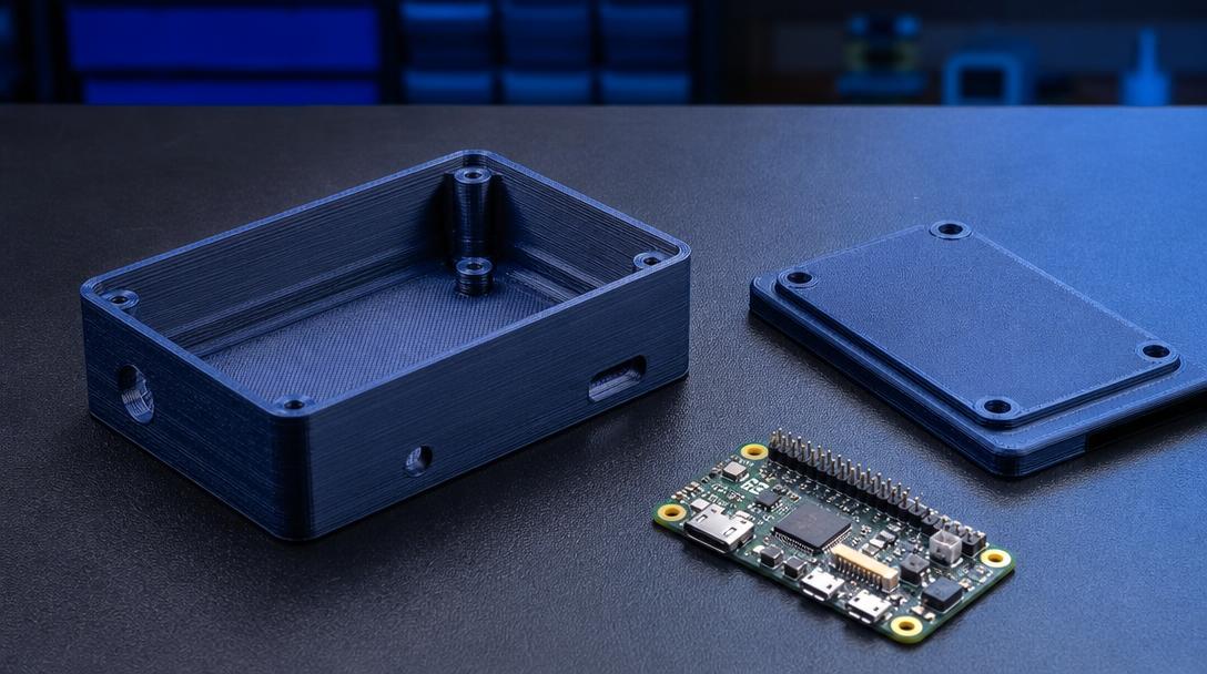
An enclosure that protects an electronic board, sensor, or cable connection is more than just a box-shaped part: dimensions, mounting points, cable exits, and print orientation all need to be considered together. FDM 3D-printed enclosure design is useful for prototypes that do not fit off-the-shelf cases and for custom parts made in small quantities; for a successful result, first define the conditions the part will be used in, not just its surroundings.
Define requirements before designing the enclosure
First, determine what will go inside the case and what loads it will be exposed to. In addition to the board’s outer dimensions, account for connectors, cable bend clearance, and mounting hardware. Will the lid need to be opened? Will the case be wall-mounted, exposed to vibration, or generate heat? These questions affect everything from wall thickness to lid design. FDM printing produces a layered structure, so do not assume that an enclosure is inherently waterproof, flame-retardant, or certified for electrical safety.
Leave enough clearance between the electronic board and the printed part for mounting and airflow. Check access areas for plugging in and removing connectors, and ensure that cables will not be sharply bent, using the actual components or a dimensioned mock-up. For circuits that run hot, separately assess the need to dissipate heat from inside the enclosure; a closed case can raise the temperature.
Walls, base, and mounting points
Making the walls unnecessarily thick does not always produce a stronger enclosure. The design should show where loads are applied and where the connections are located. Instead of simply adding material around screw holes, use support geometry that distributes the load across a wider base. Placing a screw hole too close to an edge can increase the risk of cracking; leave enough material around the hole and test it with the actual screw in the first prototype. Self-tapping screws, nut pockets, and heat-set inserts require different designs and should not be treated as interchangeable.
| Area | Design check | How to check |
|---|---|---|
| Base | A flat area to support the board and mounting loads | Check for wobbling and flex after assembly |
| Screw boss | Enough material around the hole and a transition that will not initiate cracks | First, install and remove the screw in a prototype |
| Lid | How repeated opening, closing, and alignment will work | Test the clearance around the lid on all sides |
| Cable exit | Connector access and cable bend clearance | Check that the lid closes with the cable connected |
| Ventilation | An airflow path around heat-generating components | Measure the temperature under actual operating conditions |
Part strength does not depend on infill percentage alone. Outer walls, layer orientation, the geometry of mounting points, and material all play a role. Avoid an orientation that loads a screw tab in a direction that could separate the layers. When choosing the print orientation for the enclosure, consider both the surface finish and the direction of forces on the lid and tabs. Ribs can support large, flat surfaces, but very thin ribs may not print successfully or provide the expected stiffness.
Test the lid and fit
You can choose a screw connection, snap-fit tabs, or separate fasteners for the lid. If snap-fit tabs will flex repeatedly, material and layer orientation become critical; a tab with a thin, sharp corner can fatigue easily. Instead of printing the entire enclosure for the first test, prepare a test piece that includes a short section of the lid edge and one mounting point to reduce material use and save time. There is no single universal clearance value: results vary with the printer, material, geometry, and print settings. For this reason, verify the actual fit with a dimensioned test piece.
- Design a simple shoulder or guide surface around the lid to help align it.
- Position connector and cable holes to match the actual components; assess whether strain relief is needed at the cable entry.
- If you are using mounting screws, leave access and screwdriver clearance for the screw heads.
- If the part will be exposed to heat, UV, impact, or chemicals, separately verify the material choice for those conditions.
Print orientation and final checks
A wide, flat base makes printing easier for many designs; however, lid tabs or screw bosses may form weak layers in this orientation. After choosing the orientation, inspect internal overhangs that need supports, cable channels, and surface quality in your slicer. Adding chamfers or angled surfaces to internal corners may help reduce unnecessary supports. For more design details, also review the wall thickness and material thickness guidelines.
For the final check, seat the board, close the lid, connect the cables and connectors, and verify screw-hole alignment and access for maintenance. If several revisions are needed, change just one design variable in each print so the source of any issue remains clear. Once your project dimensions are finalized, you can assess manufacturability through the 3D printing service and view an estimated price for your file on the online 3D printing price calculator page. For a custom enclosure, providing the file and usage conditions makes it easier to check suitability before printing.




 Türkçe
 العربية
 Русский
 فارسی
 Deutsch